In the late 1800’s , the battle of direct current versus alternating current began. The direct current which been develop bu Thomas Edison who has earned a lot of respect for his contribution to the field of electricity been loss by the developer of alternating current, Nikola Tesla and George Westinghouse. They established alternating current as the primary mode of electricity transmission and distribution because alternating current is more efficient and economical to transmit over a long distance compare to direct current.
So in this topic, we will focus to analyse circuits in which the source voltage or current is time-varying, or simply sinusoid current.
SINUSOID
A sinusoid is a signal that has the form of the sine and cosine fuction. The alternating current signal is usually referred to this form.
To understand better what is sinusoid, some of the example is the wave. The movements of the wave is repeating over and over again.
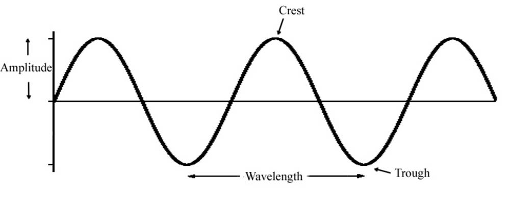
SINUSOID GRAPH

amplitude- the maximum value or it is Vm.
wavelength- the distance between two points.
frequency- is the number of wave cycle per second. (Hz)
f= (no. of cycles)/time (s)
period- The time required for one complete cycle.
T= 1/f or T= 2π/ω
SINUSOIDAL VOLTAGE FORMULA
v(t) = Vmsinωt (eq. 1)
where:
Vm is the amplitude of the sinusoid
ω is the angular frequency in radians/s
ωt the argument of the sinusoid
another general expression for the sinusoid is :
v(t) = Vmsin(ωt + φ ) (eq. 2)
where:
(ωt + φ ) is the argument and φ is the phase. These can be in radians or degrees.
IDENTITIES
A sinusoid can be expressed in either sine or cosine form using a trigonometric identities:
sin(A ± B) = sinAcosB ± cosAsinB
cos(A ± B ) = cosAcosB ± sinAsinB
With these identities, it is easy to show that
sin( ωt ± 180º) = -sinωt
cos( ωt ± 180º)= -cosωt
sin(ωt ± 90º) = ± cosωt
cos(ωt ± 90º) =-+sinωt
EXAMPLES
1. Find the amplitude, phase, period and frequency of the sinusoid
v(t) = 12cos(50t + 10º)
using the formula (eq. 1) we can point out the amplitude, phase and angular frequency:
Amplitude = Vm= 12V.
phase is φ = 10º
and the angular frequency is ω = 50rad/s
The period T= 2π/ω
T=2π/(50) = 0.1257 s
frequency is f =1/T = 7.958 Hz.
2. Calculate the phase angel between v1 = -10cos(ωt + 50º) and v2 = 12sin(ωt -10º). State which sinusoid is leading.
In order to compare v1 and v2, we must express them in the same form. If we express them in cosine form with positive amplitudes.
v1 = -10cos(ωt + 50º)
to make it positive we must subtract 180º to the phase, the result will be:
10cos(ωt + 50º- 180º) or 10cos(ωt + 230º) [ 1.1]
and
v2= 12sin(ωt -10º)
to make v2 as a cosine fuction we must used the identities and the result will be:
v2= 12cos(ωt -10º-90º)
v2= 12cos(ωt -100º) or to make it positive angle we add it to 360º
v2= 12cos(ωt +270º) [1.2]
Comparing the two voltages (v1 and v2) we can clearly say the v2 leads v1 by 30º. (the difference of two phasor)
PHASOR
A phasor is a complex number that represents the amplitude and phase of a sinusoid.
Phasor provide a simple means of analyzing linear circuits excited by sinusoidal sources.
Complex number z can be written in rectangular form as
z = x + jy (1.3a)
where j = √(-1) ; x is the real part of z ; y is the imaginary part of z.
Complex number z can also be written in polar or exponential form as
z = r‹φ
where r is the magnitude of z and φ is the phase of z.
There are two important operations :
Multiplication
z1z2 = r1r2‹(φ1 + φ 2)
z1/z2 = (r1/r2)‹(φ1 – φ 2)
note:
Two or more polar form cannot be add or subtract. (times and divide only). And add and subtract is only applicable to rectangular form.
Time-domain representation Phasor- domain representation
v(t) = Vmcos(ωt + φ) V = Vm‹φ
v(t) = Vmsin(ωt + φ) V = Vm‹φ -90º
i(t) = Imcos(ωt + φ) I = Im‹φ
i(t) = Vmsin(ωt + φ) I = Im‹φ
DERIVATIVES
dv/dt = jωV ∫vdt = V/jω
di/dt = jωI ∫idt = I/jω
Examples
1. Evaluate this complex number:
a. (40‹ 50º + 20<(-30º ))
first is to convert polar to rectangular using calculator
Rec ( 40,50) = 25.71 +j30.64 (this is using the standard form z=x +jy)
Rec(20,-30) = 17.32 -j10
adding them gives:
43.03 + j20.64 or 47.72<25.63º using the calculator Pol function.
2. Transform sinusoids to phasor
i = 6cos(50t _ 40º) A
just copy the angle and Vm which leads to
I= 6<(-40º) A
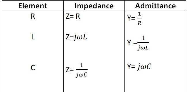
PHASOR RELATIONSHIPS FOR CIRCUIT ELEMENTS
We will begin to the resistor:
v =iR (ohm’s law)
v= RImcos(ωt + φ)
the phasor form of this voltage is V = RIm<φ
Inductor:
v = Ldi/dt
v= -ωLImsin(ωt + φ) or v = ωLImcos(ωt + φ+90)
which will be transform to the phasor
V= ωLIm<( φ+90)
Capacitor
i = Cdv/dt
I= jωCV
V= I/(jωC)